The correct protocol is to prepare a clean, perpendicular fiber tip, verify its optical pattern with the visible aiming beam, and confirm delivered power with an appropriate calibrated measurement method before clinical use. Remove the protective coating only to the length specified by the fiber and laser manufacturer, score the exposed fiber with a precision tool, and cleave it evenly over a firm support block. A crisp, circular red aiming-beam pattern is a useful screening check, but it does not replace calibrated power verification or the manufacturer’s inspection and safety requirements.
Uniform energy delivery depends on both end-face quality and system verification. A flat, clean, perpendicular cleave reduces scattering and forward-beam distortion; physical inspection, aiming-beam inspection, and measured output verification should be completed before treatment.
Why Fiber-End Preparation Matters
The Fiber Structure Controls Light Delivery
A delivery fiber typically contains a high-index core, a lower-index cladding, and a protective outer coating. Light remains largely confined within the core through total internal reflection at the core-cladding boundary.
The protective coating provides mechanical strength, but it must be removed carefully where the fiber end is prepared. Damage to the core or cladding can increase scattering, reduce transmission, or create a hazardous leakage point.
A Perpendicular End Face Promotes Uniform Output
The exposed fiber should be scored with a fine, purpose-designed preparation knife and then broken cleanly across a firm support block, such as the specified silicon cleaving surface. The objective is a flat, clean end face perpendicular to the fiber axis.
An angled, chipped, contaminated, or rough end face can scatter energy, distort the beam, create local heating, and increase the risk of damage to the fiber or connected handpiece.
The Preparation and Testing Protocol
1. Confirm the Applicable Instructions
Before preparation, identify the fiber type, intended laser wavelength, power range, connector or handpiece, and whether the fiber is single-use or reusable. The manufacturer’s instructions take precedence, because allowable stripping length, cleaving method, sterilization status, and output limits vary between systems.
Use appropriate laser safety controls throughout the process. Do not inspect an unterminated or damaged fiber while the treatment laser is capable of emitting.
2. Inspect the Fiber Before Stripping
Check the delivery fiber and sheath for kinks, crushing, cuts, severe bends, contamination, loose connectors, or other mechanical damage. Do not use a fiber that shows structural damage or unexplained changes in transmission.
A damaged fiber can become an uncontrolled source of radiation. If damage occurs during setup or treatment, stop emission, activate the emergency shutdown procedure when necessary, and replace the complete delivery system according to the device’s service instructions.
3. Remove the Protective Coating Carefully
Strip only the required length of protective coating using the specified stripping tool. Avoid nicking, scraping, twisting, or bending the exposed fiber.
The cladding should remain intact unless the approved preparation procedure specifically requires otherwise. The exposed section should be clean and free of coating residue, dust, fluid, and fingerprints.
4. Score and Cleave the Fiber
Make a small, controlled score around the fiber tip with the precision knife. The score should be sufficient to guide a clean break rather than cut deeply into the fiber.
Place the scored section over the firm support block and apply an even, controlled force so the fiber breaks across the score. Do not grind, crush, repeatedly bend, or manually tear the fiber, since these actions can produce microscopic cracks and an irregular end face.
5. Inspect the End Face
Under suitable magnification and illumination, check that the end face is flat, clean, and free from visible chips, cracks, contamination, or an obvious angle. Any questionable cleave should be discarded or reprepared using the approved method.
Do not rely on visual inspection alone when the fiber will transmit clinically significant power. The end face may appear acceptable while still producing excessive loss or an unsafe beam profile.
6. Check the Visible Aiming Beam
Activate only the low-power visible aiming beam under the laser’s approved test procedure and project it onto a flat, nonreflective surface. A properly prepared tip should produce a crisp, sharply edged, circular light pattern.
An elongated, fuzzy, split, ring-like, or irregular pattern suggests an angled or damaged cleave, contamination, misalignment, or another delivery-system problem. Do not proceed to treatment until the cause is identified and corrected.
The aiming beam is a qualitative alignment check. Because it may not share the treatment beam’s wavelength, mode, or power behavior, a satisfactory red pattern cannot by itself prove uniform therapeutic energy delivery.
7. Verify Delivered Power
Where the system procedure requires it, measure output with a calibrated power or energy meter suitable for the laser wavelength, emission mode, pulse duration, and expected power level. Compare the result with the manufacturer’s specified tolerance and the facility’s documented acceptance criteria.
Record the fiber identifier, laser settings, measured output, inspection result, and operator or device status as required by the quality system. A substantial discrepancy between commanded and measured output requires treatment to stop and the fiber, connector, handpiece, and laser to be evaluated.
8. Insert the Fiber Without Damaging the Sheath
When inserting the fiber through a flexible delivery sheath or endoscope, straighten the channel as fully as practical before insertion. This reduces internal scoring, excessive friction, and damage that could later cause fluid leakage or compromise sterilization.
Advance the fiber gently and never force it through resistance. Maintain the minimum bend radius specified by the manufacturer during use, transport, and storage.
How to Judge Uniform Energy Output
Use Multiple Checks
Uniform delivery should be assessed through a combination of:
- A clean, perpendicular fiber cleave.
- A clear and circular visible aiming-beam pattern.
- Output measurements within the approved tolerance.
- Correct connector, handpiece, wavelength, and operating mode.
- Absence of abnormal heating, odor, arcing, visible damage, or unexpected treatment behavior.
No single check is sufficient for every medical laser system. The red aiming pattern detects obvious beam-quality problems, while calibrated measurement addresses actual energy transmission.
Treat Unexpected Output as a Fault
A sudden reduction in power, unstable output, beam distortion, localized heating, or damage near the fiber tip should be treated as a system fault rather than corrected by increasing the laser setting. Increasing commanded power can worsen an underlying coupling or fiber-damage problem.
Stop emission and follow the device-specific service or replacement procedure. Only qualified personnel should troubleshoot internal laser, connector, or calibration problems.
Understanding the Trade-offs
Cleaving Improves Output but Does Not Repair Damage
A precise cleave can remove a damaged terminal section and restore a suitable end face when the approved procedure allows it. It cannot correct cracks, burns, contamination inside the fiber, damage along the delivery cable, or a degraded connector.
If the fiber has been structurally compromised, replacement is generally the appropriate response under the manufacturer’s instructions.
The Aiming Beam Is Fast but Limited
The visible aiming beam provides a practical pre-treatment check and can reveal gross scattering or an irregular end face. However, it is not a direct measurement of treatment-beam power, fluence, pulse energy, or dose uniformity.
Power verification is especially important after fiber replacement, suspected damage, maintenance, unusual output behavior, or any procedure identified by the manufacturer as requiring a test.
Flexible Systems Require Mechanical Discipline
Flexibility improves handpiece maneuverability, but repeated kinking, tight bends, pulling, or torsion can damage the optical path. The resulting defect may create beam leakage or change the delivered energy while remaining difficult to detect externally.
Never look directly into a broken, severed, or unterminated fiber. Lasers should be triggered deliberately through the approved hand or foot control and disabled or secured when not in active clinical use.
Making the Right Choice for Your Goal
Use the following priorities when applying the protocol to a specific system:
- If your primary focus is uniform beam quality: Prepare a clean, perpendicular cleave and reject any fiber that produces a fuzzy, asymmetric, or noncircular aiming-beam pattern.
- If your primary focus is accurate therapeutic dose: Add calibrated power or energy measurement and compare the result with the manufacturer’s documented tolerance.
- If your primary focus is equipment and patient safety: Inspect for mechanical damage, maintain bend-radius limits, straighten the sheath during insertion, and immediately remove damaged fibers from service.
- If your primary focus is reproducible clinical operation: Document fiber preparation, aiming-beam inspection, output verification, laser settings, and any replacement or rejection decision.
A disciplined cleave, visual beam check, calibrated output test, and careful mechanical handling together provide the reliable basis for uniform and safe optical delivery.
Summary Table:
| Step | Action | Key Check |
|---|---|---|
| 1 | Confirm manufacturer's instructions | Applicable to specific fiber type |
| 2 | Inspect fiber before stripping | No kinks, cuts, or damage |
| 3 | Strip protective coating | Correct length, no nicks |
| 4 | Score and cleave | Clean, perpendicular break |
| 5 | Inspect end face | Flat, clean, no chips |
| 6 | Check aiming beam | Crisp, circular pattern |
| 7 | Verify delivered power | Within tolerance, calibrated meter |
| 8 | Insert without damage | Maintain bend radius |
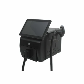
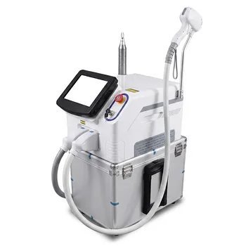
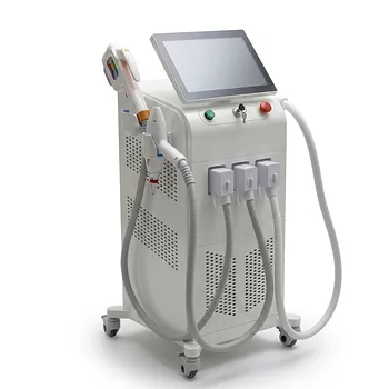
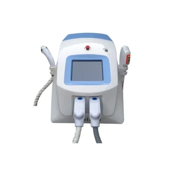
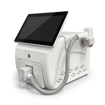
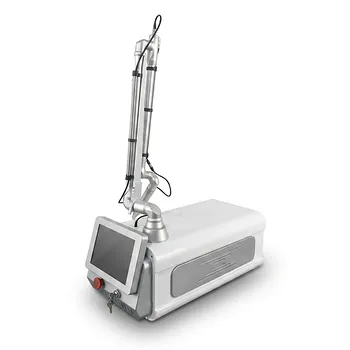
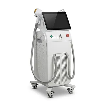
Ensure safe, consistent laser treatments with BELIS. Our professional-grade aesthetic equipment includes delivery fibers designed for reliable energy output. Choose from our advanced laser systems (Diode, Alexandrite, CO2, Erbium, Nd:YAG, Pico), IPL, and PDT devices. Partner with BELIS for OEM/ODM support, certifications, and supply reliability. Contact us today to discuss your needs!
Related Products
- Clinic Use IPL SHR ND YAG Laser Hair Removal RF Skin Tightening Machine
- Hydrofacial Machine with Facial Skin Analyzer and Skin Tester
- Diode Laser SHR Trilaser Hair Removal Machine for Clinic Use
- Trilaser Diode Hair Removal Machine for Beauty Clinic Use
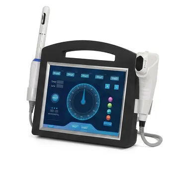
- 4D Vaginal HIFU and Face HIFU System
People Also Ask
- Why is the millisecond pulse width critical for laser hair removal on dark skin? Safety Guide for Dark Skin Treatments
- How does the combined application of laser devices and Eflornithine cream create a synergistic effect? Maximize Results
- What are the core hardware limitations of home hair removal devices? Why Professional Systems Deliver Superior Results
- Why is a 0–10 satisfaction scale used for hair management equipment? Elevate Your Clinic's Clinical Efficacy Metrics
- How long does a single laser hair removal session take? Fast & Effective Treatments for Your Busy Schedule